
Author : Anil Kumar CSE
Computer Network
- Network: A network is a set of devices connected by communication meduim.
- Computer Network: A computer network is a system that connects multiple devices—like computers, servers, or smartphones—so they can communicate, share data, and resources efficiently. It is the backbone of the digital world. Every time you send a WhatsApp message, stream Netflix, or make a UPI payment, you’re using a computer network.
- Data Communications: exchange of data between two devices via transmission medium.
Communication Protocol
Five Components of Data Communication
- Message
- Sender
- Receiver
- Medium
- Protocol
- Protocol: A protocol is set of rules that govern data communications. It is like an agreement between communicating devices. Without a protocol, two devices may be connected but cannot communicate, just like a person cannot understand Assamese who speaks only Tamil
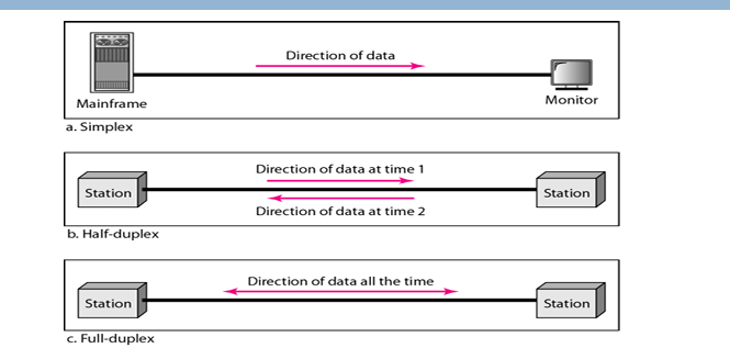
During data communication, data flow is of 3 type:
- 📺 Reference Video
Confused? No worries - this video will clear everything up in seconds-
- type of connection between them : point to point, multipoint
| Connection Type | Description | Real-life Example |
|---|---|---|
| Point-to-Point | Entire capacity of the link is reserved for transmission between two devices | Telephone call between two people |
| Multipoint | More than two devices share a common link | Classroom with one teacher and many students |
Goals of the network
- Performance
- Reliability
- Security
but how the network in real life look likes
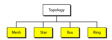
Physical Topology: The term physical topology refers to the way in which a network is laid out physically.
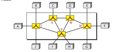
Mesh Topology
Every device has a dedicated point-to-point link to every other device.Star Topology
- Each device has a dedicated point-to-point link only to a central controller, usually called a hub.
- If a device wants to send data to another device, it sends the data to hub, which relays the data to another connected device.
Bus Topology
- Bus topology uses multipoint connections.
- Nodes are connected to the bus cable by drop lines (connection running between device and the main cable)and taps (connector).
Ring Topology
Each device has a dedicated point-to point with only two devices on either side of it.
- 📺 Reference Video
Confused? No worries - this video will clear everything up in seconds-
Categories of Networks
Types of Networks
| Network Type | Description | Example |
|---|---|---|
| Local Area Network (LAN) | Usually privately owned and links devices in a single office, building, or campus. | Our campus network |
| Metropolitan Area Network (MAN) | Covers a town or a city, designed for customers who need high-speed connectivity. | Cable TV network |
| Wide Area Network (WAN) | Provides long-distance transmission of data, image, audio, and video over large geographic areas (country, continent, or even the planet). | Internet backbone, telecom networks |
| Internet | When two or more networks (LAN, MAN, WAN) are connected, they become an internetwork or Internet. | The global Internet |
- 👉 Standard: A set of agreed rules or guidelines made by organizations(like IEEE, ISO, ITU, ANSI) so that different devices and systems can work together
OSI Model
ISO is the organization. OSI is the model.
An ISO standard that covers all aspects ofnetwork communications is the Open Systems Interconnection model.
An open system lets two different computers talk to each other using common rules. The OSI model explains how this communication works without changing their hardware or software.
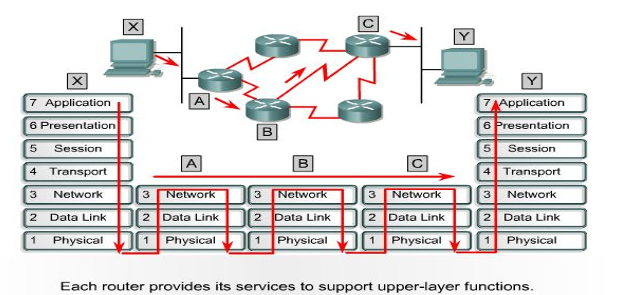
Layered Architecture of OSI Model
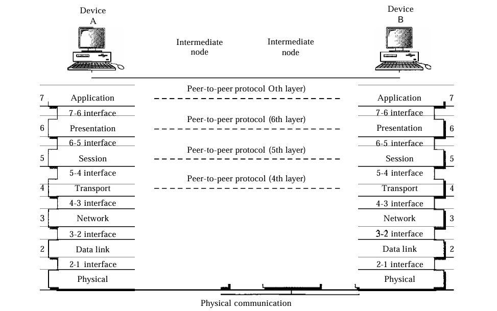
- Each layer in the sending device adds its own information to the message it receives from the layer just above it and passes the whole package to the layer just below it.
Physical Layer
- Main Responsibility: The physical layer is concerned with transmitting raw bits over a communication medium/channel.
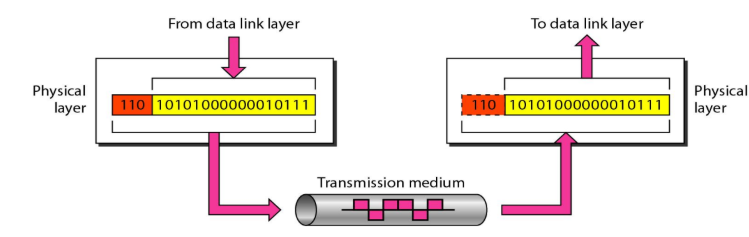
- It also define the type of transmission media.
- The physical layer data consists of a stream of bits (sequence of 0s and 1s) with no interpretation(explanation).
- Data Rate: The number of bits transmitted per second is also specified by the physical layer.
- Bit synchronization at the physical layer ensures sender and receiver agree on timing so that each bit (0 or 1) is correctly recognized. Without it, bits would get misread, causing data corruption.
- It also defines the Line configuration, Physical topology,Transmission mode.
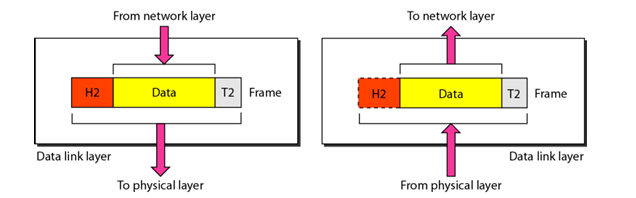
Data Link Layer
- Main Responsibility: It makes physical layer appear error-free to the network layer.
| Feature | Hop-to-Hop Delivery | End-to-End Delivery |
|---|---|---|
| OSI Layer | Data Link Layer | Network Layer |
| Scope | Delivery from one node(router,switch..) to the next (one link) | Delivery from source device to destination device |
| Responsibility | Ensures a frame is delivered to the next hop | Ensures a packet is delivered across the entire path |
| Unit of Data | Frame | Packet |
| Reliability | Checks errors at each link (e.g., CRC) | Ensures packet reaches the correct destination |
| Example | PC → Switch, Switch → Router | Client → Web Server across the Internet |
Why Both Hop-to-Hop and End-to-End Delivery are Needed?
- We need both because hop-to-hop checks each step of the journey, while end-to-end makes sure the whole message reaches the destination. Together, they keep communication reliable and complete.
Framing: The data link layer divides the stream of bits received from the network layer into manageable data units called frames.
Flow control: If the rate at which the data are absorbed by the receiver is less than the rate at which data are produced in the sender, the data link layer imposes a flow control mechanism to avoid overloading of receiver.
A trailer is added to the end of frame for error control.
Access control: When two or more devices are connected to the same link, data link layer protocols determine which device has control over the link at any given time.
Network Layer
- MainResponsibility: The network is responsible for the source-to destination delivery of packet, possibly across multiple networks (links).
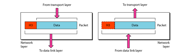
- Logical Addressing: If packet passes the network boundary, we need another addressing system to help distinguish the source and destination systems.
Q: If the Data Link layer can deliver packets using MAC addresses, why do we need logical addressing (IP addresses) in the Network layer?
- MAC addresses work only inside a local network (e.g., your laptop to a printer via a switch). But if you send data to a server in another country, the packet must cross many networks. Here, the IP address (logical address) guides routers to deliver data end-to-end, just like a full postal address across cities.
- Routing: When independent networks or links are connected to form internetwork (network of networks), the connecting devices (called routers or switches) routes or switch the packets to their final destination. The network layer ensures this mechanism for source-to-destination delivery.
Transport Layer
- Main Responsibility: The transport layer is responsible for process-to-process delivery of the entire message in segments.
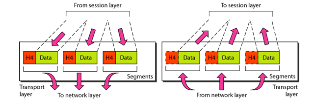
Service-point addressing:Since computers often run multiple programs at the same time, source-to-destination delivery means not only sending data from the source computer to the destination computer, but also ensuring delivery from a specific process (running program) on one computer to the corresponding process on the other.
Segmentation: A message is divided into transmittable segments, with each segment containing a sequence number.
Transport Layer can be either connectionless and connection-oriented. is its connectionless then segments are individually sent to destination.but if its connection oriented transport layer needs to make first connection with transport layer of the destination machine before delivering data.
Flow Control:like data link layer flow control does't happen at each hop, in this layer flow control heppen end-to-end.
Error Control: error control perfromed process to process.
Session Layer
Main Responsibility: The session layer is responsible for dialog control and synchronization.
Dialog Control:Dialog control is the function of the session layer in networking that manages who can talk, when, and for how long in a communication between two devices.
Synchronization:This Layer allow to add check point to a stream of data. if a crash happens then requires to transmit only those data after the recent check point.
Presentation Layer:
Main Responsibility: The presentation layer is responsible for translation, compression and encryption.
Translation: The presentation layer at the sender changes the information from its sender dependent format into a common format.
Encryption:Encryption means that the sender transforms the original information to another form and sends the resulting message out over the network.
Compression: Data compressing reduces the number of bits contained in the information.
Application Layer: The application layer is responsible for providing services to the user.
Application Layer: The application layer is responsible for providing services to the user.
- Network Virtual Terminal(NVT):NVT is a universal standard text format in Telnet, acting like a common language so different computers can talk without worrying about their internal representation.
- Some service also there like file transfer ,mail service.
- 📺 Reference Video
Confused? No worries - this video will clear everything up in seconds-
TCP/IP protocol Suite:
- TCP/IP do not exactly match those in OSI model,it defined as having four layers:
- Application
- Transport
- Internet
- host to network
Difference between TCP/IP and OSI Model
| Aspect | OSI Model (7 Layers) | TCP/IP Model (4 Layers) |
|---|---|---|
| Full Form | Open Systems Interconnection | Transmission Control Protocol / Internet Protocol |
| Developed By | ISO (International Organization for Standardization) | DARPA (Defense Advanced Research Projects Agency) |
| Layers | 7 Layers: Application, Presentation, Session, Transport, Network, Data Link, Physical | 4 Layers: Application, Transport, Internet, Network Access |
| Approach | Theoretical, reference model | Practical, protocol-oriented model |
| Application Layer | Split into Application, Presentation, Session | Combined into a single Application layer |
| Transport Layer | Provides reliable (TCP) and unreliable (UDP) delivery | Provides both TCP (reliable) and UDP (unreliable) |
| Network Layer | Separate Network layer | Internet layer (similar role) |
| Data Flow | Defines what each layer should do (guideline) | Defines how protocols actually work |
| Protocol Dependency | Protocol-independent | Protocol-specific (TCP, IP, UDP, etc.) |
| Usage | Used as a teaching and reference model | Used in real-world networking and the Internet |
- TCP/IP model has only connectionless mode in network layer but support both mode in transport layer, but when it comes to OSI model just opposite.
IP Addressing
- If we can have a common network id for all the node in a particular LAN then it will be better because router need not to maintain info of all the nodes.
- But, we have to also identify the individual node. Therefore, we also require to have some way to get each node’s identity.
- Thus, Internet Protocol (IP) divides the address (IPv4 address) into two parts: Network id and Host id *IPv4 has 32 bits address (4 bytes). Each byte is separated by a dot.
What do u know about NAT ?
- Network address translation(NAT) enables a user to have a large set of address internally(Private IP Address) and one address, or a small set of addresses, externally(public IP Address).
What do u know about NAT ?
- Network Address Translation (NAT) enables a user to have a large set of addresses internally (Private IP Address) and one address, or a small set of addresses, externally (Public IP Address).
About Fragmentation
- An IPv4 datagram (packet) can be as large as 65,535 bytes.
- But not all physical networks (like Ethernet, Wi-Fi, etc.) can handle such a big packet.
- Each physical network has a limit on packet size called MTU (Maximum Transmission Unit).
- If a datagram is bigger than the MTU, it must be broken into smaller pieces so it can pass through.
- This breaking process is called Fragmentation.
Difference between IPv4 and IPv6
| Feature | IPv4 | IPv6 |
|---|---|---|
| Address Size | 32-bit (≈ 4.3 billion addresses) | 128-bit (≈ 3.4 × 10^38 addresses) |
| Address Format | Decimal, 4 numbers separated by dots (e.g., 192.168.1.1) | Hexadecimal, 8 groups separated by colons (e.g., 2001:0db8::1) |
| Header | Variable length (20–60 bytes) | Fixed length (40 bytes), simpler structure |
| Configuration | Manual or DHCP | Auto-configuration + DHCPv6 supported |
| Security | IPSec optional | IPSec built-in by default |
| Broadcast | Supports broadcast | No broadcast; uses multicast and anycast |
| Fragmentation | Done by both sender and routers | Done only by sender |
| Address Classes | Classful addressing (A, B, C, etc.), NAT used | Classless, hierarchical addressing, no NAT needed |
| Advantages | Limited addresses, complex header | Larger address space, better header, new options, extensions, stronger security |
- Tunneling:It is a strategy used when two computers using IPv6 want to communicate with each other and the packet must pass through a region that uses IPv4.
What if some system use IPv4 but majority of the internet has moved to IPv6 !
- Header translation: It is necessary when the majority of the Internet has moved to IPv6 but some systems still use IPv4.
- The sender wants to use IPv6, but the receiver does not understand IPv6.
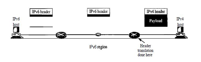
- The header of the IPv6 packet is converted to an IPv4 header.
Analog v/s Digital Signal
- Analog data is captured as continuous values. For instance, when someone speaks an analog wave is created in the air. This can be captured by a microphone and converted to an analog signalor sampled and converted to a digital signal.
- Digital data is captured as discrete values. For instance, data stored in computer memory in the form of 0s and 1s. These can be converted to a digitalor modulated into an analog signal.
- In data communications, we commonly use periodic analog signals and nonperiodic digital signals.
- Attenuation means a loss of energy.
- Amplifiers are used to compensate for this loss of energy by amplifying the signal.
- Noise is an unwanted disturbance in an electrical signal.
Performance
- One important issue in networking is the performanceof the network—how good is it?
- Bandwidth
- Throughput
- Latency (Delay)
- Bandwidth-Delay Product
- Bandwidth:-bandwidth in bits per second, refers to the number of bits per second a channel, a link or even a network can transmit.or The maximum capacity of a network link to transfer data.
- Throughput:-The throughput is a measure of how fast we can actuallysend data through a network.The actual rate of successful data delivery over a network.
Delay
The latency or delay defines how long it takes for an entire message to completely arrive at the destination from the time the first bit is sent out from the source.
- propagation time
- transmission time
- queuing time
- processing time
- propagation time:- measures the time required for a bit to travel from the source to the destination.
- transmission time:-measures the time required for entire message to reach its destination.
- queuing time:-Queuing time is the time needed for each intermediate or end device to hold the message before it can be processed.
- Processing time: the time required to process (eg. Error correction) the message at end device (receiver) or parts of message (eg. frames) at intermediate devices (eg. router).
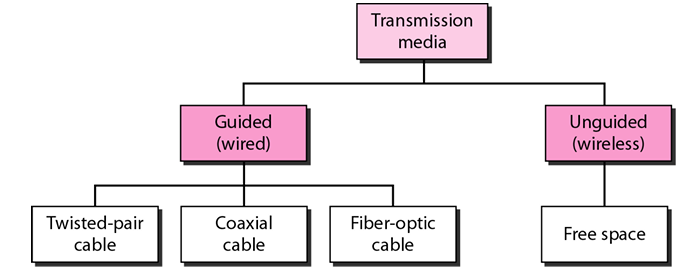
Transmission media
Error Detection vs. Error Correction
The correction of error is more difficult than detection of an error.
In error detection, we are looking only to see any error has occurred.
We are not even interested in number of error. The single-bit error or burst error is same for us.
In error correction, we need to know exact number of bits that are corrupted and more importantly, the locationin the message.
Forward error correction: Receiver tries to guess by using redundant bits.
Retransmission: Receiver requests sender to retransmit the message.
Hamming distance indicates how many errors in the codewordscan be detected and corrected.
Why Framming?
- Limited buffer sizeat the receiver.
- A larger block of data has higher probability of error.
Framming Methods
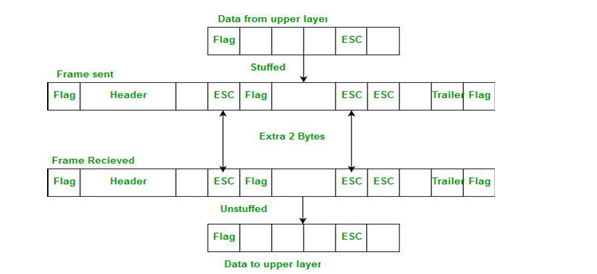
- Byte stuffing:- The sender inserts a special byte (e.g., ESC) just before each “accidental” flag byte in the data (like in C language, “ macros are replaced with values/definitions”).
- Bit stuffing:-Whenever the sender encounters five consecutive 1s in the data, it automatically stuffs a 0 bit into the outgoing bit stream.
Flow Control:
- Stop-and-Wait Flow Control
- Sliding-Window Flow Control
Stop-and-Wait Flow Control
- Source transmits a frame.
- Destination receives theframe,and replies with a small frame called acknowledgement (ACK).
- Source waits for the ACK before sending the next frame.
- Destination can stop the flow by not sending ACK(e.g., if the destination is busy …).
- It is not efficient for long haul transmission and high speed transmission.
Sliding-Window Flow Control
- Idea: allow multiple frames to transmit.
- Receiver has a buffer of W frames
- Transmitter can send up to W frames withoutreceivingACK
- Each frame needs to be numbered: sequence number is included in the frame header.
- ACK includes the sequence number of the next expected frameby the receiver
- Idea: allow multiple frames to transmit.
Performance of both methods(Errors)
- Lost frames
- Damaged frames
Two approachesfor error control :
- automatic repeat request
- forward error correction
Automatic Repeat Request(ARQ)
The role of ARQ is to turn an unreliable data link into a reliable one.
Stop-and-Wait ARQ
The source station is equipped with a timer.
Source transmits a single frame, and waits for an ACK.
If the frame is lost.
- The timer eventually fires, and the source retransmits the frame.
If receiver receives a damaged frame, discard it.
- he timer eventually fires, and the source retransmits the frame.
If everything goes right, but the ACK is damagedor lost, the sourcewill not recognize it.
- he timer eventually fires, the sourcewill retransmit the frame.
- Receiver gets two copies of the same frame!
Simple, but inefficient for long distance and high speed applications.
Go-Back-N ARQ
- Based on sliding-window flow control.
- Use window size to control the number of unacknowledged frames outstanding.
- If no error, the destination will send ACK as usual with next frame expected (positive ACK,RR: receive ready).
- If error, the destination will reply with rejection (negative ACK,REJ: reject).
Selective-Reject ARQ
- Also called selective repeat
- Only rejected frames are retransmitted
- Receiver must maintain large enough buffer, and must contain logic for reinserting the retransmitted frame in the proper sequence.
Piggybacking ?
- Piggybacking means sending an acknowledgement (ACK) along with data in the same frame instead of sending it separately because of to overcome overhead.
- Station A → Station B: sends a data frame.
- Station B receives it, but instead of sending an immediate ACK, it waits until it has data to send back. What is HDLC?
- HDLC (High-Level Data Link Control) is a bit-oriented data link layer protocol developed by ISO.
- Provides reliable and efficient communication over both synchronous and asynchronous links.
Types of HDLC Frames
- I-Frame (Information Frame)
- Carries user data and control information.
- Used for normal data transfer.
- S-Frame (Supervisory Frame)
- Provides control (ACK, NAK, flow control).
- U-Frame (Unnumbered Frame)
- Used for control purposes (like establishing/terminating a connection).
Point-to-Point Protocol (PPP)
- HDLC can be used in both point-to-point and multi-point configuration.
- PPP is the most commonly used protocol for point-to-point access.
Why Switching?
- When we have multiple devices, we have problem of how to connect them to make one-to-one communication possible.
- One solution could be use of mesh topology to have point-to-point connection or have star topology to have just one central node.
- Both are not practical when applied to very large network.
- In the network, what we can have is the devices that are part of the network and capable of creating temporary connections between two or more devices.
- Switch is a device that has such capability.
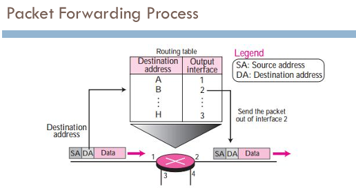
Switching Methods
- Main responsibility of a switch is to:
- Forward packets/data from input port to output port
- Select port based on the address in the packet header
- In circuit switching, a physical circuit (or channel) is established between the source and destination of the message before the delivery of the message.
- The circuit switching is mostly used at the physical layer, and was never implemented at the network layer.
- The network layer in the Internet today is a packet-switched network.
- The connecting devices in a packet-switched network still need to decide how to route the packets to the final destination.
- Datagram switching is done at the network layer.
- A virtual-circuit network is cross between a circuit-switched network and datagram network.
- Virtual-circuit network is implemented in the data link layer, while circuit-switched network in physical layer and datagram network in network layer.
Controlled Access
- n controlled access, the stations consults one another to find which station has the right to send.
- A station cannot send unless it has been authorized by the other stations.
=======
DNS
- Name Space:-Names must be unique because addresses are unique.
Flat name space:-A name is a sequence of characters without interface.
Hierarchical Name Space:-
- Each name is made of several parts.
- Each parts may have meaning/interpretation.
- Eg. (nits.ac.in=> nits . ac. in)
- Authority to assign and control of name space can be decentralized.
- The central authority can assign and control a part of the name that defines the nature of the organization and name of the organization.
- The organization add (suffixes) or (prefixes) to define its host or resources.
- The management of the organization need not to worry about the prefix chosen by different organization.
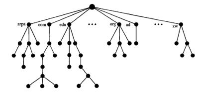
- names are defined in an inverted tree structure with the root at the top.
Label
- Each node in the tree has a label, which is a string with max of 63 characters.
- The root label is null string (empty string)
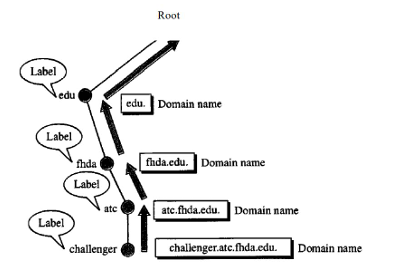
Domain Name
- The domain names are always read from the node uptothe root so that it ends with last label of the root (null).
- Each node in the tree has a domain name.
- A full domain name is a sequence of labels separated by dots (.).
- A full domain name always ends with a null label, which means last character is a dot because the null string is nothing.
Domain Name Categories
- Fully Qualified Domain Name (FQDN):If a domain name is terminated by a labelof root i.e. null string it is call FQDN.
- Partially Qualified Domain Name (PQDN):A PQDN starts from a node but it does not reach the root.
Domain
- A domain is subtree of the domain space.
- The name of the domain is the domain name of the node at the top of the subtree.
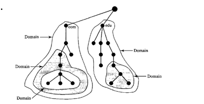
Distribution of Name Space
- The information contained in the domain name space must be stored.
- However, it is very inefficient and also unreliable to have just one computer store such a huge amount of information.
- It is not reliable because any failure makes the data inaccessible.
- The solution to these problems is to distribute the information among many computers called DNS servers.
- Because a domain created in this way could be very large, DNS allows domains to be divided further into smaller domains (subdomains).
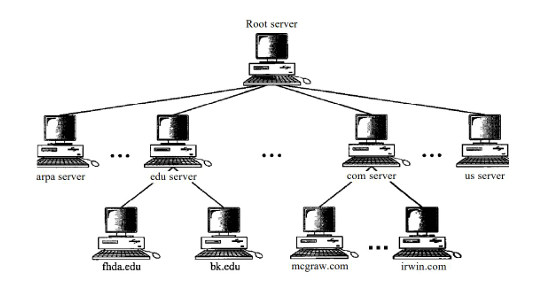
DNS in the Internet
DNS is a protocol that can be used in different platforms.
In the Internet, the domain name space (tree) is divided into three different sections:
- Generic domains:-Defines registered hosts according to their generic behavior.
- Country Domains:-he country domains section uses two-character country abbreviations (e.g., infor Bharat).
- Inverse Domain:-The inverse domain is used to map an address to a name, The server asks its resolverto send a query to the DNS server to map an address to a name to determine if the client is on the authorized list.
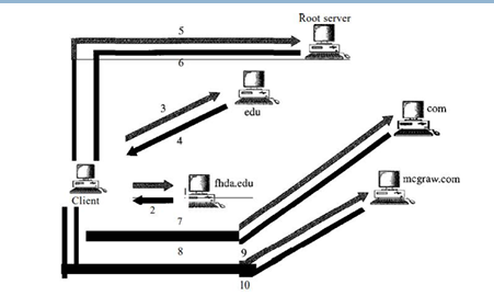
Name-address Resolution
The resolver, a DNS client within the client/server-based DNS system, maps names to addresses (or vice versa) by sending a request to the nearest DNS server, which either provides the information directly or refers/queries other servers, and once the mapping is obtained, the resolver interprets the response, checks for errors, and delivers the final result to the requesting process
- Recursive Resolution:-
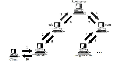
- Iterative Resolution:-
Electronic Mail (email)
There are three components in email systems:
- User Agent (UA)
- Message Transfer Agent (MTA)
- Message Access Agent (MAA)
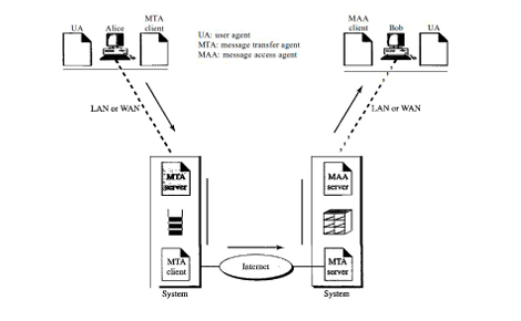
- User Agent (UA):-
- It provides service to the user to make the process of sending and receiving a message easier.
- It is a software package (program) that composes, reads, replies to, and forwards messages. Various services are shown in Figure below.
- To deliver mail, a mail handling system must use an addressing system with unique addresses.
- In the Internet, the address consists of two parts: a local partand a domain name, separated by an @sign.
MIME
- Multipurpose Internet Mail Extensions (MIME) is a supplementary protocol that allows non-ASCII data to be sent through e-mail.
- Simple electronic email can send messages only in 7-bit ASCII format.
- MIME transforms non-ASCII data at the sender site to ASCII data and delivers them to the client MTA to be sent through the Internet.
- Message at the receiving side is transformed back to original data.
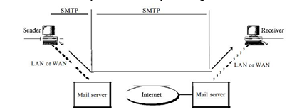
Message Transfer Agent : SMTP(protocol)
- The actual mail transfer is done through message transfer agents.
- To send mail, a system must have the client MTA, and to receive mail, a system must have a server MTA.
- The formal protocol that defines the MTA client and server in the Internet is called the Simple Mail Transfer Protocol (SMTP).
- SMTP is used two times, between the sender and the sender's mail server and between the two mail servers.
Message Access Agent: POP and IMAP
SMTP is used in first two stages (components).
It is not involved in the third stage because SMTP is a pushprotocol; it pushes the message from the client to the server.
In last stage, message has to be pulled from server to client. So, third stage has to use pull protocol.
Message Access Protocols:
- Post office Protocol version 3 (POP3)
- Internet Mail Access Protocol ver4 (IMAP4)
POP3
- Post Office Protocol, version 3 (POP3) is simple and limited in functionality.
- The client POP3 software is installed on the recipient computer.
- The server POP3 software is installed on the mail server.
- POP3 has two modes:
- Delete mode-the mail is deleted from the mailbox after each retrieval.
- Keep mode-the mail remains in the mailbox after retrieval.
IMAP4
IMAP4 is similar to POP3, but it has more features; IMAP4 is more powerful and more complex.
A user can partially download e-mail.
A user can create, delete, or rename mailboxes on the mail server.
A user can search the contents of the e-mail for a specific string of characters prior to downloading.
Web-based Email
Some websites today provide this service to anyone who accesses the site eg. Google, Yahoo, Hotmail.
Mail transfer from Alice's browser to her mail server is done through HTTP.
The transfer of the message from the sending mail server to the receiving mail server is still through SMTP.
Finally, the message from the receiving server (the Web server) to Bob's browser is done through HTTP.
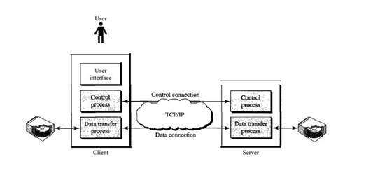
File Transfer -FTP
File Transfer Protocol (FTP) is the standard mechanism provided by TCP/IP for copying a file from one host to another.
FTP establishes two TCP connections between the hosts.
One connection is used for data transfer, the other for control information (commands and responses).
FTP uses two well-known TCP ports:
- Port 21 is used for the control connection, and
- port 20 is used for the data connection.
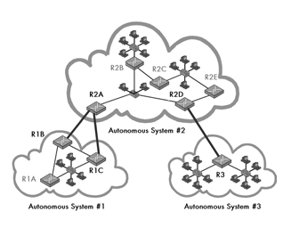
Routing Protocols and Algorithms
Types of Routing
- Autonomous system(AS) is a group of networks and routers come under single administrative authority.
Inter-domain routing-Routing between AS
Intra-domain routing-Routing within AS
Two Node Instability
- Imagine only 2 stations (nodes) trying to send data on a shared medium.> * If both nodes sense the channel as idle at the same time, they may transmit simultaneously → collision.
- After collision, both back off and retry, but if they both choose the same backoff time repeatedly → continuous collisions can occur.
- This situation is called 2-node instability (system becomes unstable because just 2 nodes cannot resolve the collision smoothly).
Three-Node Instability
Now, consider 3 or more nodes sharing the medium.
When collisions occur among them, the backoff algorithm has more randomness (different nodes likely pick different wait times).
But as the number of nodes increases, probability of repeated collisions also increases.
This makes the system unstable with 3 or more nodes, where throughput may collapse due to excessive collisions.
Routing Information Protocol (RIP)
- It is based on distance vector routing (DVR).
- Metric used in RIP is hop count i.e. the number of links (networks) that have to be used to reach the destination.
It helps routers figure out the best path to send data from one network to another.
Maximum hop count = 15.
What is Border Gateway Protocol (BGP)?
To exchange routing information between different Autonomous Systems (AS)
Unlike RIP (distance vector) or OSPF (link state), BGP is a path vector protocol – it keeps the whole path (list of AS numbers) to avoid loop
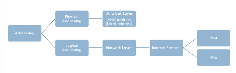
Addressing
Data link layer, we need a MAC address to choose ONE node among SEVERAL node.
At the Network layer we need an IP address to choose one Host among Millions.
At the Transport layer we need a transport layer address called a PORT NUMBER ,to choose among multiple processes running on the destination host.
Destination port number for delivery; source port no for the reply
Socket Address
Process to process delivery needs two identifiers , IP address and port number at each end to make a connection.
The combination of IP address and a Port number is called a socket address
| Feature | UDP (User Datagram Protocol) | TCP (Transmission Control Protocol) | SMTP (Simple Mail Transfer Protocol) |
|---|---|---|---|
| Layer | Transport Layer | Transport Layer | Application Layer |
| Connection | Connectionless | Connection-oriented | Connection-oriented (uses TCP) |
| Reliability | No reliability, no ACKs | Reliable (ACKs, retransmission) | Reliable (inherited from TCP) |
| Data Transfer | Fast, low overhead | Slower due to error checking & flow control | Used for sending emails (store-and-forward) |
| Ordering | No guarantee of order | Ensures ordered delivery | Ensures email delivery in correct sequence |
| Use Cases | Streaming, VoIP, DNS, gaming | File transfer, web browsing, emails | Email transfer between mail servers |
| Protocol Type | Transport protocol | Transport protocol | Application protocol (runs on TCP) |
| Port Number | Varies (e.g., DNS uses 53) | Varies (e.g., HTTP uses 80, HTTPS 443) | Default port 25 (SMTP), also 465/587 |
TCP Connection Establishment
TCP transmits data in full-Duplex mode .
When two TCP’s in two machines are connected, they are able . to send segment to each other simultaneously.
So each party must initialize communication and get approval . from other party before any data are transferred.
The connection establishment in TCP is called Three way handshaking.
TCP uses sliding window to handle the flow control.
TCP Congestion Control
- Two Categories of Congestion Control Mechanisms: 1. Open Loop Congestion Control _ These policies are applied to prevent congestion before it happens. _ In these mechanisms, congestion control is handled by either source or destination. 2. Closed Loop Congestion Control * These mechanisms try to overcome congestion after it happens <<<<<<< HEAD:CN/README.md
ARP v/s RARP
| Feature | ARP (Address Resolution Protocol) | RARP (Reverse Address Resolution Protocol) |
|---|---|---|
| Full Form | Address Resolution Protocol | Reverse Address Resolution Protocol |
| Purpose | Finds the MAC address from a given IP address | Finds the IP address from a given MAC address |
| Direction | IP → MAC | MAC → IP |
| Layer | Network Layer (works between IP & Data Link) | Network Layer (works between Data Link & IP) |
| Used By | Sender device (e.g., computer sending data) | Diskless machines (need IP at boot time) |
| Packet Broadcast | Broadcasts an ARP request asking "Who has this IP?" | Broadcasts a RARP request asking "Who has this MAC?" |
| Response | Device with that IP replies with its MAC address | RARP server replies with the IP address |
| Current Use | Still in use in LANs (IPv4) | Obsolete, replaced by BOOTP and DHCP |
SSL & TLS
- Both SSL (Secure Sockets Layer) and TLS (Transport Layer Security) are cryptographic protocols used to secure communication over the internet.
| Feature | SSL (Secure Sockets Layer) | TLS (Transport Layer Security) |
|---|---|---|
| Current Status | Deprecated & insecure | Actively used (TLS 1.2, TLS 1.3) |
| Security Level | Weak (vulnerable to attacks) | Stronger encryption & security |
| Versions | SSL 2.0, SSL 3.0 (obsolete) | TLS 1.0 → TLS 1.3 (latest, secure) |
| Usage Today | Not used | Used in HTTPS, SMTP, IMAP, POP3, VPNs |
| Certificate Naming | Often called "SSL Certificates" | Actually TLS certificates |
| Browser Support | No modern browser supports SSL | All modern browsers support TLS |
/// nat used for translate small set or private ip address to public adress through the router to access internate when we directly assign the public ip to the device then its waste of the ip because ip are very less in the world so that we need to use public ip address but in the era of the ipv6 we dont need the nat because the network is large enough
/// dhcp-> used to assign the ip address to the device we can assign the ip in two ways one is static which is assign by user itself other one is dynamicly, there is the high probabily that ip can conflict,here comes the dhcp server which assgin the ip address outomaticy to the device
// firewall-> firewall is the system that is design to prevent unauth access from intering a private network, i blocks the unauth msg and filterout them ,it builts the safty barrier between the private and public network
How HTTPS Works (Step by Step)
1. DNS & TCP Setup
- Browser resolves domain → IP (via DNS).
- Opens TCP connection to server on port 443.
TLS 1.3 Handshake (Step by Step)
🔹 Step 1: ClientHello
- Browser → Server (in clear text)
- Sends:
- Supported encryption methods (cipher suites)
- A random number (used for key generation)
- SNI (Server Name Indication): tells which website it wants (important when multiple sites share one IP).
- ALPN (Application Layer Protocol Negotiation): says which HTTP version it supports (HTTP/1.1, HTTP/2).
🔹 Step 2: ServerHello
- Server → Browser
- Chooses:
- One encryption method (cipher suite)
- Its own random number
- Key share (used for secure key exchange with Diffie–Hellman)
🔹 Step 3: Server Certificate & Proof
- Server sends:
- Certificate chain (server certificate + intermediate certificates)
- Digital signature → proves it owns the certificate (private key)
- (Optional) OCSP stapling → proves certificate is not revoked
🔹 Step 4: Certificate Validation (Browser side)
Browser checks:
- Certificate issued by a trusted CA (Certificate Authority)
- Website name matches the certificate
- Certificate is valid (not expired / revoked)
👉 If any check fails → Browser shows a warning (Not Secure page)
🔹 Step 5: Key Exchange & Secure Channel
- Browser + Server combine their random numbers + key share
- Generate the same secret key
- Use it for:
- Encryption (data is private)
- Integrity (data not changed in transit)
✅ Handshake complete → Now HTTP data is sent securely.
3. Secure HTTP
- All HTTP requests/responses encrypted with session keys.
- Protects:
- Cookies
- Headers
- Body
- Paths & query strings
- Note: IP, port, and SNI hostname are still visible.
4. Optimization
- Session Resumption: reuse keys → faster handshake (1-RTT).
- 0-RTT Data: client sends data immediately (risk: replay attack).
TLS 1.3 vs TLS 1.2
| Feature | TLS 1.2 | TLS 1.3 (modern) |
|---|---|---|
| Handshake round-trips | 2+ RTT | 1 RTT (faster) |
| Forward secrecy | Optional | Mandatory (ECDHE) |
| Cipher suites | Many, some weak | Only strong (AES-GCM, ChaCha20) |
| Encrypted handshake | Partial | Almost all |
Why HTTPS Is Secure
- 🔒 Confidentiality → Encryption (AES-GCM, ChaCha20).
- ✅ Integrity → AEAD prevents tampering.
- 🛡️ Authentication → Server proves identity via CA-issued certificates.
- 🚫 Stops MITM (man-in-the-middle) attacks.